Showing posts with label rcc design. Show all posts

9 Oct 2017

CONCRETE MIX DESIGN M40 GRADE


WHAT IS CONCRTE MIX DESIGN ?

The process of selecting suitable ingredients of concrete and determining their relative amounts with the objective of producing a concrete of the required, strength, durability, and workability as economically as possible, is termed the concrete mix design.

POINT TO BE REMEMBER WHILE MAKING MIX DESIGN
  • The grade designation giving the characteristics strength required of concrete.
  • The type of cement influences the rate of development of compressive strength of concrete.
  • Maximum nominal size of aggregate to be used in concrete may be as large as possible within the limits prescribed by the IS : 456-2000.
  • The cement content is to be limited from shrinkage, crack, and creep.
  • The workability of concrete for satisfactory placing and compacting is related to the size and shape of the section,quantity and spacing of reinforcement and technique used for transportation, placing and compaction.

CONCRETE MIX DESIGN-M40 GARDE EXAMPLE

1.Design Stipulation For Proportioning

Grade Designation = M-40
Type of cement = O.P.C-43 grade confarming to IS 8112
Maximum nominal size of aggregate = 20 mm
Maximum Cement content =450 kg / m3
Minimum Cement content = 320  kg / m3
Maximum water cement ratio = 0.45
Workability = 100 mm (slump)
Exposure condition = Severe (for reinforced concrete)
Method of placing = Pumping 
Degree of supervision = Good
Type of aggregate = Crushed angular aggregate
Chemical admixture type = Superplasticiser

2. Test Data For Material

Cement used = OPC 43 grade confirming IS 8112
Sp. Gravity Cement = 3.15
Sp. Gravity Fine Aggregate = 2.61
Sp. Gravity Coarse Aggregate (20mm) = 2.65
Sp. Gravity Coarse Aggregate (10mm) = 2.66
Chemical admixture = Superplasticiser confirming IS 9103
Water absorption of coarser aggregate = 0.5%
Water absorption of coarser aggregate = 1%
Free surface moisture = Nil

3. Target Mean Strength

Target Mean Strength = 40 + ( 5 X 1.65 ) = 48.25 Mpa

Selection of water cement ratio
Assume water cement ratio = .40 - 0.45

4. Selection Of Water Content

Approximate water content for 20mm max. Size of aggregate = 180 kg /m3 (As per Table No. 2 , IS : 10262 ). As plasticizer is proposed we can reduce water content by 20%.
Now water content = 180 X 0.8 = 140kg /m3

5. Cement Content Calculation

Water cement ratio = 0.40
Water content per m3 of concrete = 144 kg
Cement content = 144/0.35 = 411.4 kg / m3
Say cement content = 412 kg / m3 (As per contract
Minimum cement content 350 kg / m3 )
Hence O.K.

6. Calculation of sand and coarse aggregate 

V = [ W + (C/Sc) + (1/p) . (fa/Sfa) ] x (1/1000)
V = [ W + (C/Sc) + {1/(1-p)} . (ca/Sca) ] x (1/1000)
Where
V = absolute volume of fresh concrete, which is equal to gross volume (m3) minus the volume of entrapped air ,
W = mass of water ( kg ) per m3 of concrete ,
C = mass of cement ( kg ) per m3 of concrete ,
Sc = specific gravity of cement,
(p) = Ratio of fine aggregate to total aggregate by absolute volume ,
(fa) , (ca) = total mass of fine aggregate and coarse aggregate (kg) per m3 of
Concrete respectively, and
Sfa , Sca = specific gravities of saturated surface dry fine aggregate and Coarse aggregate respectively.
As per Table No. 3 , IS-10262, for 20mm maximum size entrapped air is 2% .
Assume F.A. by % of volume of total aggregate = 36.5 %
0.98 = [ 160 + ( 400 / 3.15 ) + ( 1 / 0.365 ) ( Fa / 2.61 )] ( 1 /1000 )
=> Fa = 660.2 kg
Say Fa = 660 kg.
0.98 = [ 160 + ( 400 / 3.15 ) + ( 1 / 0.635 ) ( Ca / 2.655 )] ( 1 /1000 )
=> Ca = 1168.37 kg.
Say Ca = 1168 kg.
Considering 20 mm : 10mm = 0.6 : 0.4
20mm = 701 kg .
10mm = 467 kg .
Hence Mix details per m3
Cement = 400 kg
Water = 160 kg
Fine aggregate = 660 kg
Coarse aggregate 20 mm = 701 kg
Coarse aggregate 10 mm = 467 kg
Admixture = 0.6 % by weight of cement = 2.4 kg.
Recron 3S = 900 gm
Water: cement: F.A.: C.A. = 0.4: 1: 1.65: 2.92

7. Observation for concrete mix design

% Strength of concrete : The strength of concrete increases with
age.

Table for strength of concrete at various age
Age
Strength per cent
1 day
16%
3 days
40%
7 days
65%
14 days
90%
28 days
99% 

A. Mix was cohesive and homogeneous.
B. Slump value = 120 mm
C. No. of cube casted = 9 

7 days average compressive strength = 42.07 N/mm2
28 days average compressive strength = 52.52 N/mm2
which is greater than 48.25 N/mm2
Hence the mix accepted.


24 Sept 2017

TYPES OF LOAD ACTING ON BUILDING (IS : 875)


The loads acting on structures can be broadly classified as vertical loads, horizontal loads and longitudinal loads.
The Vertical Loads Consist Of :
1. Dead load : It is the self weight of structure which are transferred to structure throughout the life span. It majorly consists of the weight of walls, columns, beams, roofs etc.

Dead Load = volume of each section x unit weight of material

Sl. NoMaterial Unit Weight Of Material
1
Plain Cement Concrete
18.8 kN/m3
2
Reinforced Cement Concrete
24 kN/m3
3
Brick Masonry
18.8 kN/m3
4
Timber
5-8 kN/m3
5Stone Masonry20.4-26.5 kN/m3


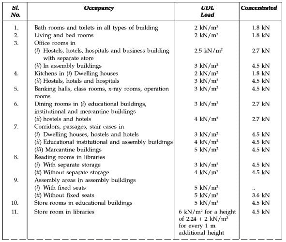
2. Live load : Live loads are either movable or moving load on building. It includes weights of movable partitions or furniture etc. The minimum value of live loads to be assumed are specified by the IS 875 (part 2)–1987.


Live Load For The Following Occupancies :


  • Educational buildings
  • Assembly building
  • Institutional buildings
  • Mercantile buildings
  • Industrial buildings
  • Business and office buildings
  • Storage rooms
  • Residential buildings–dwelling houses, hotels, hostels, boiler rooms and plant rooms, garages.

Imposed Or Live Load for different Occupancies :
megastructureart.blogspot.com
IMPOSED OR LIVE LOAD ON STRUCTURE


However, reductions in assumed total live loads on floors may be made in designing columns, walls, their supports and foundations as shown in table below.

Number of floors carried by member under consideration
Reduction of total live load on all floors above the member under consideration
 %
1
0
2
10
3
20
4
30
5-10
40
Over 10
50


3. Snow load : Load caused by the snowfall on the roof of the building. It is consider as vertical load acting on a building.

According to the IS 875 (part 4) – 1987, the minimum snow load on a roof area is obtained by the expression
Types of Loads on Structures - Snow Loads


Where
S = Design snow load on plan area of roof.
Shape coefficient
= Shape coefficient

S0 = Ground snow load.

The Horizontal Loads Consist Of :
1. Wind load : It is the horizontal load caused by the blowing wind. Wind load is required to be considered in structural design especially when the height of the building exceeds two times the dimensions latreal to the exposed wind surface.

The calculation of wind loads depends on the two factors :

  • Velocity Of Wind 
  • Size Of The Building 

According to the IS-875 (Part 3) -1987) wind load calculating by the following expression : 

              
            Vz = k1.k2.k3.Vb


Where k1 = Risk coefficient
k3 = Topography factor
k2 = Coefficient based on terrain, height and structure size.
V= basic wind pressure is shown in a map of India. 

The design wind pressure is given by : 


pz = 0.6 V2z


where
pz is in N/m2 at height Z 
Vz is in m/sec. 
Note : wind pressure act uniformly up to the height of 30 meter, Above 30 m height, the wind pressure increases. 
2. Earthquake load :  It is the vibrational load on structure caused by the earthquake. This vibration occur in all three direction, but the movement in vertical direction do not cause forces in superstructure to any significant extent. But the horizontal movement of the building at the time of earthquake is to be considered while designing.

For monolithic reinforced concrete structures located in the seismic zone 2, and 3 without more than 5 stories high and importance factor less than 1, the seismic forces are not critical.

12 Sept 2017

GENERAL GUIDLINES FOR REINFORCEMENT BAR

REINFORCEMENT BAR DETAIL GUIDELINE


The material added to concrete for resist the tension produce within the internal fibres of structure during loading is called steel bars or reinforcement bars. These bar installed in the tension zone to strengthen the structure and avoid to produces cracks during loading. when the bars is also use in compression zone the strength increases up to 20%, if deformed bars is used then strength will increase up to 40%.


TYPES OF REINFORCEMENT 


1. Mild Steel Plain Bars : A mild steel bar made up of with out surface deformation is called mild steel plain bar.

IS: 432 (part 1) Specification :
  • In this categories, for bar up to 20 mm diameter, characteristic yield strength is 250 N/mm2.
  • For bar over 20 mm diameter, characteristic yield strength is 240 N/mm2. 
  • In tension, bar up to 20 mm diameter, the permissible stresses 140 N/mm2 in steel reinforcement is taken into account and for over 20 mm diameter, permissible stresses 130 N/mm2 is taken into account  
  • Compression in column bar, compression in bars in a beam or slab when compressive resistance of concrete is taken into account, the permissible stresses 130 N/mm2 in steel reinforcement is taken into account. 
  • Compression in bars in a beam or slab when the compressive resistance of the concrete is taken into account, the permissible stresses 140 N/mm2 in the steel reinforcement is consider for bar diameter up to 20 mm,  permissible stresses 130 N/mm2 for bar diameter over 20 mm is consider.

2. Mild Steel Hot Rolled Deformed Bars : A mild steel bar made up of surface deformation is called mild steel deformed bar.

IS: 1139 Specification :
  • In this categories, for bar up to 20 mm diameter, characteristic yield strength is 250 N/mm2.
  • For bar over 20 mm diameter, characteristic yield strength is 240 N/mm2. 

  • In tension, bar up to 20 mm diameter, the permissible stresses 140 N/mm2 in steel reinforcement is taken into account and for over 20 mm diameter, permissible stresses 130 N/mm2 is taken into account  
  • Compression in column bar, compression in bars in a beam or slab when compressive resistance of concrete is taken into account, the permissible stresses 130 N/mm2 in steel reinforcement is taken into account. 
  • Compression in bars in a beam or slab when the compressive resistance of the concrete is taken into account, the permissible stresses 140 N/mm2 in the steel reinforcement is consider for bar diameter up to 20 mm,  permissible stresses 130 N/mm2 for bar diameter over 20 mm is consider.


3. Medium Tensile Steel Plain Bars : This type of bars shows a medium characteristic yield strength.

IS: 432 (part 1) Specification :
  • In this categories, for bar up to 20 mm diameter, characteristic yield strength is 350 N/mm2.
  • For bar between 20 mm to 40 mm diameter, characteristic yield strength is 340 N/mm2. 
  • In tension, bar for any diameter, the permissible stresses is half the guaranteed yield stress subjected to a maximum of 190 N/mm2
  • Compression in column bar, compression in bars in a beam or slab when compressive resistance of concrete is taken into account, the permissible stresses 130 N/mm2 in steel reinforcement is taken into account for any diameter. 
  • Compression in bars in a beam or slab when the compressive resistance of the concrete is taken into account, the permissible stresses is half the guaranteed yield stress subjected to a maximum of 190 N/mm2.


4. Medium Tensile Steel Deformed Bars : 

IS: 432 (part 1) Specification :
  • In this categories, for bar up to 20 mm diameter, characteristic yield strength is 350 N/mm2.
  • For bar between 20 mm to 40 mm diameter, characteristic yield strength is 340 N/mm2. 
  • For bar over 40 mm diameter, characteristic yield strength is 320 N/mm2
  • In tension, bar for any diameter, the permissible stresses is half the guaranteed yield stress subjected to a maximum of 190 N/mm2
  • Compression in column bar, compression in bars in a beam or slab when compressive resistance of concrete is taken into account, the permissible stresses 130 N/mm2 in steel reinforcement is taken into account for any diameter. 
  • Compression in bars in a beam or slab when the compressive resistance of the concrete is taken into account, the permissible stresses is half the guaranteed yield stress subjected to a maximum of 190 N/mm2.

5. High Yield Strength Steel Deformed Bars : HYSD is the high yield strength deformed bars have ribs on the surface and this increases the bond strength at least by 40%.

IS: 1139 Specification :
  • In this categories, bar for all size diameter, characteristic yield strength is 415 N/mm2.
  • In tension, bar up to 20 mm diameter, the permissible stresses 230 N/mm2 in steel reinforcement is taken into account and for over 20 mm diameter, permissible stresses 230 N/mm2 is taken into account  
  • Compression in column bar, compression in bars in a beam or slab when compressive resistance of concrete is taken into account, the permissible stresses 190 N/mm2 in steel reinforcement is taken into account. 
  • Compression in bars in a beam or slab when the compressive resistance of the concrete is taken into account, the permissible stresses 190 N/mm2 in the steel reinforcement is consider for bar diameter up to 20 mm,  permissible stresses 190 N/mm2 for bar over 20 mm diameter is consider.